Ray Tracing Meshes
In a nutshell: We will run through how to write a ray tracer which can render trianglemesh geometry using the help of tinyobjloader.
Ray Tracing Triangle Meshes
Learning ray tracing nowadays is really intuitive as there is a wealth of (free!) information out there. Online tutorials, blogs, books all do fantastic jobs of introducing the basics of ray tracing (such as Pete Shirley’s ‘Ray Tracing In One Weekend’). There are also really in-depth deep dives into ray tracing (such as PBRT). However, in my experience I struggled to find a good middle-ground, especially as someone with a non-technical background. Last year, I found myself in a situation where I felt comfortable with the basics, but the climb towards reading material such as PBRT seemed too far out of my reach. However, I personally found breaking things down into smaller project-based goals made that climb more achievable.
One particular area I found tough when progressing to more advanced ray tracing was to render more complex geometry such as meshes. As CG Artist, I had a bunch of personal projects where I modelled, textured, shaded assets from scratch. How cool would it be to now render them in my own ray tracer? Unfortunately I struggled to find many resources online that easily explained this in a plain (artist friendly!) and step-by-step way, so this is the goal for this blog post- To help anyone who is at the stage where they have a non-technical background, but are comfortable with basic ray tracing and want to progress further.
For completion, I will be covering how to write the full ray tracer but feel free to skip down to Step 6 if you are only concerned with getting the TriangleMesh functionality.
Assumptions
-
We are familiar with setting up projects in an IDE with C++ (I will be using Visual Studio Code on MacOS, but any OS should be fine)
-
We are familiar with the basics in a ray tracer (vectors, matrices, camera projection, intersection routines, image writing)
-
We are familiar with setting up CMake in our chosen IDE
Step 1 - Setup a Visual Studio Code project
We will start with a standard C++ and CMake project where the main.cpp is just a simple “hello world\n”. For convenience I will use GLM for our Vector/Matrix math, but you can use your own, or a different one such as Embree or Eigen. I’ve made a math.hpp file to include the GLM files needed. To make it a bit more generic, I typedef glm::vec3 and glm::mat4 as Vector3f and Matrix4x4f but again this is optional. So at this stage, we should have a CMakeLists.txt, main.cpp and math.hpp/cpp that looks like:
math.hpp
#include <iostream>
#include <../include/glm/glm.hpp>

typedef glm::vec3 Vector3f;
main.cpp
#include "../src/math.hpp"

int main() {

    std::cout<<"hello world\n";

    return EXIT_SUCCESS;
}
Step 2 - Simple Ray-Sphere intersection
Just to make sure our image writing and ray tracing have some basic functionality, lets go ahead and make a simple ray-sphere intersection routine. Assuming we are familiar with a simple ray-sphere tracer, this should all be straight-forward. Lets make a ray class (which we can add to the math.hpp file).
class Ray {
public:
    Ray() {}
    Ray(const Vector3f& orig, const Vector3f& dir) : o(orig), d(dir) {}
public:
    Vector3f o;
    Vector3f d;
};
We will then make a struct to set the render options.
struct Options {
    uint32_t width;
    uint32_t height;
    float fov;
};
And then a function for ray-sphere intersection:
float ray_sphere_intersection(const Vector3f& center, float radius, const Ray& r) {
Vector3f oc = r.o - center;
float a = glm::dot(r.d, r.d);
float b = 2.0f * glm::dot(oc, r.d);
float c = glm::dot(oc, oc) - radius * radius;
float discriminant = b * b - 4 * a * c;
if (discriminant < 0.0f) {
return -1.0f;
} else {
return (-b - sqrt(discriminant)) / (2.0f * a);
}
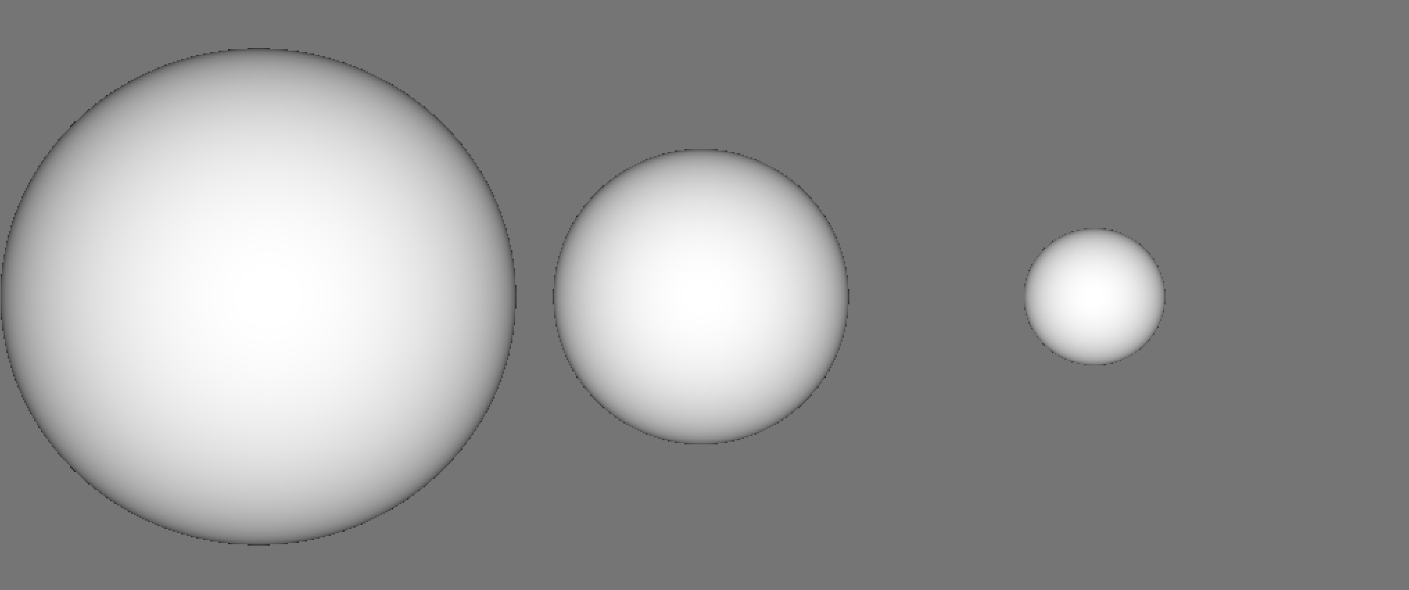
}And a cast_ray function. If we hit a sphere, we will just draw the normal for that pixel.
Vector3f cast_ray(const Ray& r) {
    float hit = ray_sphere_intersection(Vector3f(0.0f, 0.0f, -1.0f), 0.5f, r);
    if (hit > 0.0f) {
        Vector3f normal = glm::normalize((r.o + hit * r.d) - Vector3f(0.0f, 0.0f, -1.0f));
        return normal;
    }
    return Vector3f(0.18f);
}
Then finally in the main function, make the intersection routine
    std::ofstream ofs("OUT.ppm", std::ios::out | std::ios::binary);
    ofs << "P6\n" << options.width << " " << options.height << "\n255\n";

    float scale = tan(deg2rad(options.fov * 0.5f));
    float image_aspect_ratio = options.width / (float)options.height;

    // Time keeping
    auto start = std::chrono::system_clock::now();
    std::cout<<"Rendering image ... \n";
    for (uint32_t j = 0; j < options.height; ++j) {
        std::cout<<"Scanlines remaining : "<<options.height - j<<"\n";
        for (uint32_t i = 0; i < options.width; ++i) {
            float u = (2.0f * (i + 0.5f) / (float)options.width - 1.0f) * scale;
            float v = (1.0f - 2.0f * (j + 0.5f) / (float)options.height) * scale * 1.0f / image_aspect_ratio;
            Ray ray = Ray(Vector3f(0.0f), Vector3f(u, v, -1.0f));
            Vector3f colour = cast_ray(ray);

            char r = (char)(255.99f * colour.x);
            char g = (char)(255.99f * colour.y);
            char b = (char)(255.99f * colour.z);

            ofs << r << g << b;

        }
    }
    // Time keeping
    auto end = std::chrono::system_clock::now();

    std::cout<<"Rendering complete! \n";

    ofs.close();

    // Time keeping
    std::time_t end_time = std::chrono::system_clock::to_time_t(end);
    std::chrono::duration<double> elapsed_seconds = end-start;
    std::cout << "Program completed on " << std::ctime(&end_time) << "\nTime taken to render : " << elapsed_seconds.count() << "s\n\n";
    //Time keeping
Which should give us this image:

Step 3 - Generic Shape class
Okay, this is working well as a starting point! We’ve got a simple project that can be built using CMake, and write out successfully ray traced images. Now we can make a more generic “shape” class with a bare bones intersection function. Pretty standard OOP practise here. From there, lets make a Sphere class. I also make a “Scene” class which basically abstracts a list of shapes (so we can have multiple objects easily). If you’d rather structure your ray tracer in a data oriented manner, that’s fine too. Firstly, we should update our math.hpp file with some more functionality for the Ray class to store t min and t max values. We also will add a struct for storing ray-shape interaction attributes such as intersection point, normals etc. These can be used for shading calculations. Also a deg2rad function is useful for the camera class later on!
math.hpp
class Ray {
public:
Ray() {}
Ray(const Vector3f& orig, const Vector3f& dir, const float& tmin, const float& tmax) : o(orig), d(dir), t_min(tmin), t_max(tmax) {}
public:
Vector3f o;
Vector3f d;
float t_min;
float t_max;
};
struct SurfaceInteraction {
Vector3f p; // Intersection point
Vector3f Ng; // Geometric normal
float t; // Distance along ray for intersection
bool front_facing; // Determine if normal is aligned with ray (or against)
inline void set_face_normal(const Ray& r, const Vector3f& outward_normal) {
front_facing = glm::dot(r.d, outward_normal) < 0.0f;
Ng = front_facing ? outward_normal : -outward_normal;
}
};
inline float deg2rad(const float °) { return deg * M_PI / 180.0f; } Generic shape class looks like:
class Shape {
public:
    virtual bool intersect(const Ray& r, SurfaceInteraction& interaction) const = 0;
};
And the Sphere and Shape classes like:
sphere.hpp
#include "../src/shape.hpp"

class Sphere: public Shape {
public:
    Sphere() {}
    Sphere(Vector3f c, float r) : center(c), radius(r) {};

    virtual bool intersect(const Ray& r, SurfaceInteraction& interaction) const;
public:
    Vector3f center;
    float radius;
};
sphere.cpp
#include "../src/sphere.hpp"


bool Sphere::intersect(const Ray &r, SurfaceInteraction &interaction) const {

    Vector3f oc = r.o - this->center;
    float a = glm::length2(r.d);
    float half_b = glm::dot(oc, r.d);
    float c = glm::length2(oc) - radius * radius;
    float discriminant = half_b * half_b - a * c;

    if (discriminant > 0.0f) {
        float root = sqrt(discriminant);
        float temp = (-half_b - root) / a;
        if (temp < r.t_max && temp > r.t_min) {
            interaction.t = temp;
            interaction.p = r.o + interaction.t * r.d;
            Vector3f outward_normal = (interaction.p - center) / radius;  // Normalized by diving by radius
            interaction.set_face_normal(r, outward_normal);
            return true;
        }
        temp = (-half_b + root) / a;
        if (temp < r.t_max && temp > r.t_min) {
            interaction.t = temp;
            interaction.p = r.o + interaction.t * r.d;
            Vector3f outward_normal = (interaction.p - center) / radius;  // Normalized by diving by radius
            interaction.set_face_normal(r, outward_normal);
            return true;
        }
    }
    // No solutions
    return false;
}
scene.hpp
#include <memory>
#include <vector>
#include "../src/shape.hpp"

class Scene : public Shape {
public:
    Scene() {}
    Scene(std::shared_ptr<Shape> object) { Add(object); }

    void Clear();
    void Add(std::shared_ptr<Shape> object);

    virtual bool intersect(const Ray& r, SurfaceInteraction &interaction) const;

public:
    std::vector<std::shared_ptr<Shape> > objects;
};
scene.cpp
#include "../src/scene.hpp"

void Scene::Clear() {
    objects.clear();
}

void Scene::Add(std::shared_ptr<Shape> object) {
    objects.push_back(object);
}

bool Scene::intersect(const Ray &r, SurfaceInteraction &interaction) const {

    SurfaceInteraction temp;
    bool any_hit = false;
    float t_near = r.t_max;

    for (const auto& object : objects) {
        if (object->intersect(r, temp)) {
            any_hit = true;
            t_near = temp.t;
            interaction = temp;
        }
    }
    return any_hit;
}
Visually, our ray tracer will produce identical results. This step is more just to restructure our code in a way that implementing triangle meshes is more straight-forward. To recap, we should have math.hpp/cpp, shape.hpp/cpp, scene.hpp/cpp, sphere.hpp/cpp and finally our main.cpp files!
Step 4 - Adding a camera class
This part is optional. However, under the assumption that one might use this tutorial as a launch pad for implementing additional features (BVHs, materials, lights etc) I will go through quickly adding a basic camera class. Since Triangle Meshes can be of many sizes, it may be useful to have a more flexible camera system to implement. My preference is to make one that uses a camera-to-world matrix, so we can easily copy transformation matrices from Maya. This is pretty common workflow for me, I will figure out the layout and composition of a scene in Maya, do some preview tests and then export the data for my hobby renderer to read. But you can use a LookAt camera set-up or skip this step entirely if you prefer. For the camera class, the only function we need for now is one to generate a ray direction based on FOV, resolution and image aspect ratio.
camera.hpp
#include "../src/math.hpp"

class Camera {
public:
    Camera(uint32_t _width, uint32_t _height, float _fov, Matrix4x4f _c2w);
    Ray get_ray(float u, float v);

public:
    uint32_t width;
    uint32_t height;
    float fov;
    Matrix4x4f c2w;
    float scale;
    float image_aspect_ratio;
};
camera.cpp
#include "../src/camera.hpp"

Camera::Camera(uint32_t _width, uint32_t _height, float _fov, Matrix4x4f _c2w) {
    width = _width;
    height = _height;
    fov = _fov; // Vertical FOV
    c2w = _c2w; // Camera-to-world matrix

    scale = tan(deg2rad(fov * 0.5f));
    image_aspect_ratio = width / (float)height;
}

Ray Camera::get_ray(float u, float v) {

    // Maya-style
    float ndc_x = (2.0f * (u + 0.5f) / (float)width - 1.0f) * scale;
    float ndc_y = (1.0f - 2.0f * (v + 0.5f) / (float)height) * scale * 1.0f / image_aspect_ratio;


    Ray r;
    Vector3f orig = Vector3f(0.0f, 0.0f, 0.0f);
    Vector3f dir =  glm::normalize(Vector3f(ndc_x, ndc_y, -1.0f));

    r.o = TransformPointMatrix(c2w, orig);
    r.d = TransformDirMatrix(c2w, dir);
    r.t_max = 9999.9f;
    r.t_min = 0.001f;


    return r;
}
Again, if you don’t feel like implementing this, you can skip this! However, I think it makes positioning the camera much easier.
Step 5 - Rendering a triangle!
Before we can render whole triangle meshes, we will need to be able to render at least one triangle successfully! To do this, I’ll create a struct for a Vertex, which basically means we can store more information than a point in space. A vertex will hold a Position value, Geometric Normal and UV coordinates.
Here’s the vertex struct, no surprises here!
struct Vertex {
public:
    Vector3f P;
    Vector3f Ng;
    Vector2f UV;
};
And for the triangle class we will just have an additional function for getting barycentric coordinates to interpolate vertex attributes. I’m assuming we are all familiar with ray-triangle intersection and how to set up a triangle shape. If not, feel free to jump to the end, where I link the source code.
Vector3f Triangle::get_barycentric(Vector3f &p) const {
    Vector3f v2_ = p - v0;
    float d00 = glm::dot(e1, e1);
    float d01 = glm::dot(e1, e2);
    float d11 = glm::dot(e2, e2);
    float d20 = glm::dot(v2_, e1);
    float d21 = glm::dot(v2_, e2);
    float d = d00 * d11 - d01 * d01;
    float v = (d11 * d20 - d01 * d21) / d;
    float w = (d00 * d21 - d01 * d20) / d;
    float u = 1 - v - w;
    return Vector3f(u, v, w);
}
Okay, so now we have implemented a Triangle class that inherits from Shape. It has its own intersection routine and a function to obtain barycentric coordinates. So, if we make a test triangle and try render it, we can hopefully end up with something like this:

Great stuff! We can render a single triangle, or more if we want to. We are now ready to start loading in triangle meshes.
Step 6 - TriangleMesh Rendering
Hopefully up until now, everything has been pretty straight-forward and familiar. If not, I would really recommend taking a look at Scratchapixel or Ray Tracing In One Weekend. Now for the main part! We will use the OBJ file format. Whilst certainly not the industry standard geometry file type, it is nevertheless pretty easy to export from Maya, Modo, Zbrush, which is well suited for small toy ray tracers. To read obj data, we will use Syoyo Fujita’s wonderful tinyobjloader, which you can find here. Loading in the data into our program will be quite straight forward, we essentially need to wrangle the vertices from the OBJ file. Each vertex can have a number of attributes associated with it. The main ones I use are Vertex P values, Vertex Normals and UV coordinates. We can grab these and add them to a list holding all the vertices for the obj. Luckily, tiny_obj_loader makes this really straight-forward:
    // Loop over shapes
    for (size_t s = 0; s < shapes.size(); s++) {
        // Loop over faces(triangles)
        size_t index_offset = 0;
        for (size_t f = 0; f < shapes[s].mesh.num_face_vertices.size(); f++) {
            int fv = shapes[s].mesh.num_face_vertices[f];

            // Loop over vertices in the face.
            for (size_t v = 0; v < fv; v++) {
                // access to vertex
                tinyobj::index_t idx = shapes[s].mesh.indices[index_offset + v];
                tinyobj::real_t vx = attributes.vertices[3*idx.vertex_index+0];
                tinyobj::real_t vy = attributes.vertices[3*idx.vertex_index+1];
                tinyobj::real_t vz = attributes.vertices[3*idx.vertex_index+2];
                tinyobj::real_t nx = attributes.normals[3*idx.normal_index+0];
                tinyobj::real_t ny = attributes.normals[3*idx.normal_index+1];
                tinyobj::real_t nz = attributes.normals[3*idx.normal_index+2];
                tinyobj::real_t tx = attributes.texcoords[2*idx.texcoord_index+0];
                tinyobj::real_t ty = attributes.texcoords[2*idx.texcoord_index+1];

                Vertex vert;
                vert.P = Vector3f(vx, vy, vz);
                vert.Ng = Vector3f(nx, ny, nz);
                vert.UV = Vector2f(tx, ty);
                vertices.push_back(vert);

            }
            index_offset += fv;


        }
    }
So essentially we loop through the whole obj file, scooping up the positions of all the vertices, Normal values and UV coordinates. We then can add this to a container (I’m using a std::vector for ease of use). However, currently we have a list of unconnected vertices. So we are not quite done yet. We need to have a list of triangles for the ray tracer to test intersections against. Luckily this is pretty simple. We can make a loop through the vertices list and create triangles from 3 vertices like so:
    // Loops vertices
    for (int i = 0; i < vertices.size() / 3; ++i) {
        tris.push_back(std::make_shared<Triangle>(vertices[i * 3], vertices[i * 3 + 1], vertices[i * 3 + 2]));
    }
Then for the intersection routine for a trianglemesh, we just loop through all the triangles testing for intersections, and whichever intersects and is closest to camera is the triangle we use for shading! Obviously this is really slow. We are essentially checking every single pixel for intersection with every single triangle. That’s pretty slow already when we are just firing one visibility ray for each pixel. Imagine if we had a path tracer where we had 128 spp- this would be disasterously slow! Luckily we can leverage binary search trees in the form of Bounding Volume Hierarchies (BVHs), which are used in production renderers to accelerate ray tracing. Acceleration structures are probably worth their own blog post.
This should now work! Here are some test renders I made:
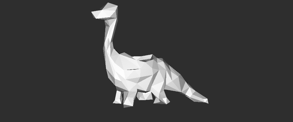
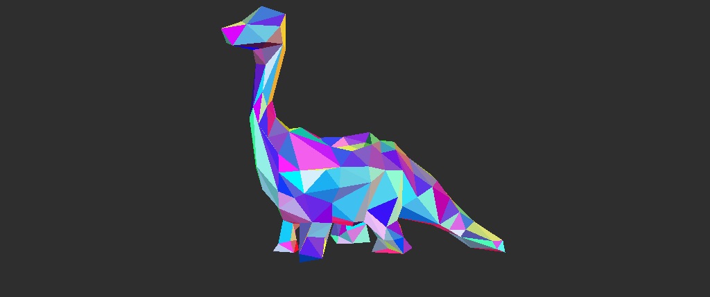
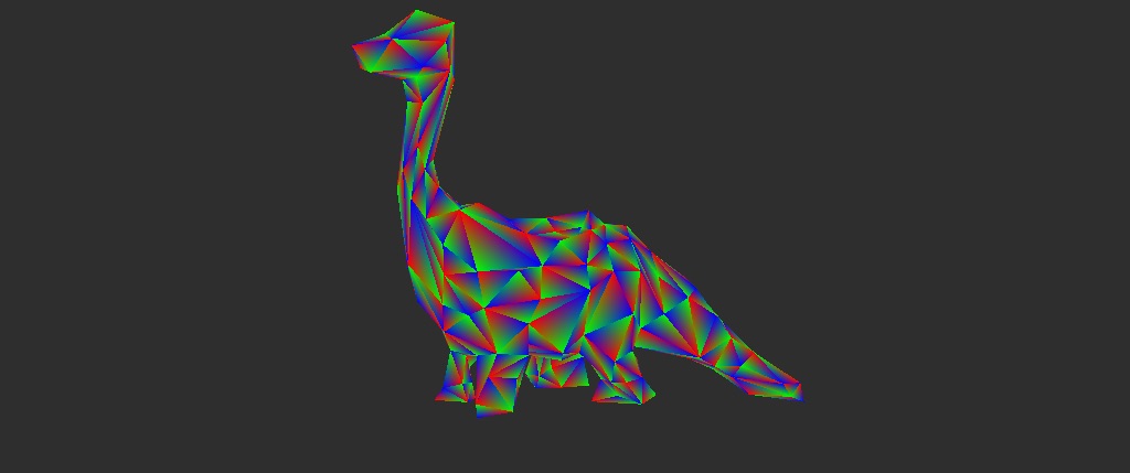
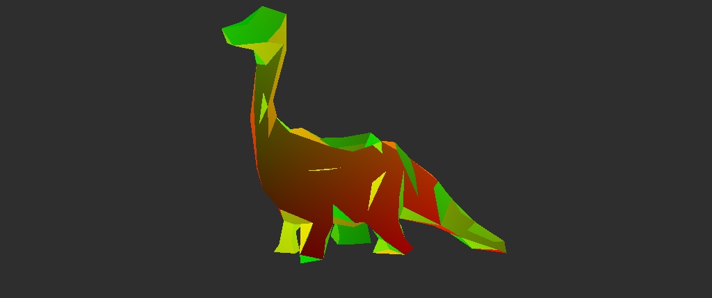
So that’s how we can create a simple obj ray tracer! There’s a bunch of ways we can extend this. For example, currently the only “shading” we have is filling in pixels with the background colour or some arbitrary value such as barycentric, NdotV or UVs. This could be extended by adding in lights. We could also implement some materials such as lambert, specular, glass BxDFs. Since we already know how to load in UVs we could even start adding texture maps. For performance, we could look into either adding simple multi-threading or acceleration structures. Now that we can render triangle meshes, one could extend the code to support subdivision surfaces, or maybe curve primitives. For now though, hopefully this has been useful to explain how to ray trace custom obj files! Thanks for reading.
Source code is here.